Friday, March 28, 2014

3D Photos - Frank James

Here, I am trying to push Depth Map Automatic Generator (DMAG3) to its limits by attempting to generate a depth map for a set of images that are quite large. Well, compared to what I usually use.


Left image.


Right image.

This stereo pair is larger than what I have used before. I wanted here to have large images so that the disparity range would be large as well. The bigger the disparity range, the smoother the depth map is gonna look like (more shades of gray in the depth map). The min and max disparities are -62 and 0, respectively. The width of the images is about 1600 pixels. Of course, it takes much longer to get a depth map for a 1600 pixel wide stereo pair than a 800 pixel wide one but the results are much better, in general.


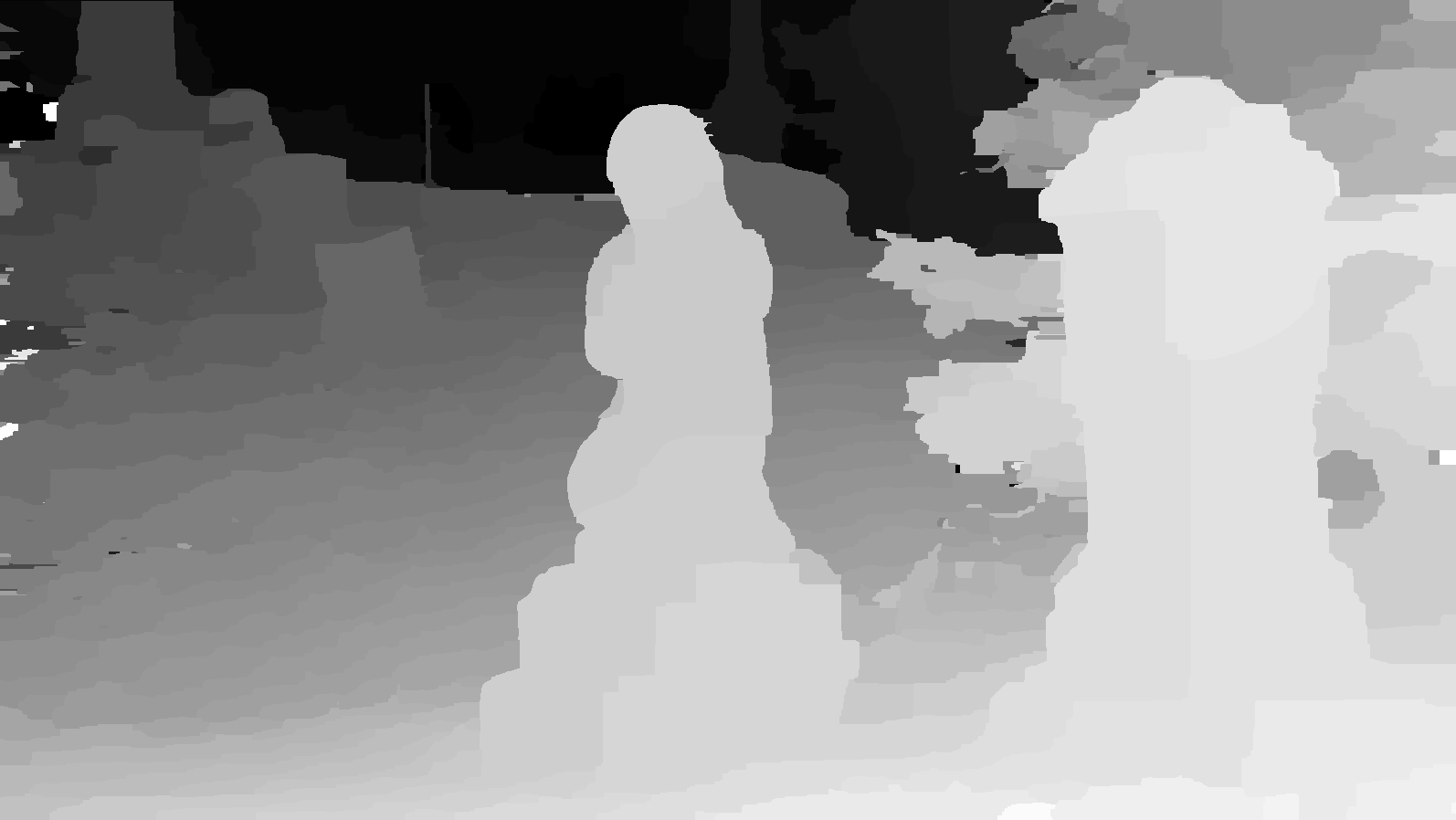
Dense depth map generated by DMAG3 using lambda=30 (smoothing parameter) and K=30 (occlusion penalty).

The "snow flakes" (isolated pixels that are much lighter than they should be) show up as "peaks" in the 3D rendered scene (see video below). There are many ways to get rid of them. One rather simple way is to open up Gimp or Photoshop and get rid of them one by one using, for instance, the fuzzy selection tool and the paint bucket tool. Of course, this kinda assumes you don't have too many of those.


Dense depth map without the "snow flakes" (removed in Gimp).


Wigglegram. Now, that's a good one!

I've used Gimpel3D to generate the wigglegram frames using an eye separation of 2 and 1. The frames were assembled in Gimp and saved as an animated gif. The whole process is a bit tedious, which is why the wigglegram carries only 5 frames.

Here's a video that shows the whole thing:

Sunday, March 23, 2014

Stereo Matching 101: Disparities, Occlusions and "Ordering Constraint"

Maybe it's time to visit or revisit the basics of stereo matching, in particular, disparities, occlusions and the so-called "ordering constraint".


The above diagram shows the classic stereo rectified camera setup. The term "rectified" means that, in the context of stereo matching, matches are made along horizontal lines (scan lines). Aligning the stereo pair in StereoPhoto Maker has the same effect as rectification. In this diagram, the left (right) image corresponds to the CCD plane (digital camera) or the film plane (old school emulsion film camera) and the center of projection is the lens (pinhole) except that obviously, the two have been swapped for easier mathematics (Clearly, the image plane should be behind the lens, not in front.) The coordinate system for each image has its origin at the upper left. The disparity is simply the difference between the x values of the matched points. The disparity is positive if the point on the right image must be shifted to the left to get to the matched point on the left image.


The above diagram shows what an occlusion (half occlusion) is. An occlusion is simply a point in the scene that can be seen by one camera but not the other. You can have occlusions when you attempt to match a point on the left image to a point on the right image, and vice versa.


The above diagram shows what the "ordering constraint" is. In layman terms, it just means that if a point in the scene appears to be to the right of another point in the left image, the relative positioning should be the same in the right image.


The above diagram shows an example of "ordering constraint" violation. It's the classic example of the picket fence in front of something else in the 3D scene. Anytime you have an object with a good size opening in the foreground, the "ordering constraint" is likely to be violated. Some stereo matching algorithms out there assumes that the "ordering constraint" always stands, which may not be a bad idea. For example, the stereo matching procedure used in OpenCV, a block-matching algorithm based upon "Small Vision Systems: Hardware and Implementation" by K. Konolige, makes use of the "ordering constraint".