Frame Sequence Generator 6 (FSG6) interpolates views between a left image and a right image using the left and right disparity/depth maps. FSG6 relies on backward mapping/warping as explained in View Interpolation (forward mapping/warping and backward mapping/warping).
The input to FSG6 is:
- left image,
- right image,
- left depth map,
- right depth map,
- minimum disparity and maximum disparity (the ones you used to generate the left depth map), and
- the number of frames needed.
The number of frames includes the left and right images. As an example, if the number of frames requested is 3 and the file type of image 1 (left image) is png, the interpolated views will be named frame0.png, frame1.png, and frame2.png. The first frame (in this case, frame0.png) is always a copy of image 1 (left image) and the last frame (in this case, frame3.png) is always a copy of image 2 (right frame).
What follows is for depth map generators that only generate the left depth map:
To generate the right depth map after having generated the left depth map (using any automatic depth map generator that only outputs a left depth map), all you have to do is flip the right image horizontally (that's gonna be your new image 1), flip the left image horizontally (that's gonna be your new image 2), and give the two new images to the depth map generator keeping the minimum and maximum disparities unchanged (and any other parameter unchanged as well). The resulting depth map is the right depth map once it has been flipped horizontally. Flipping an image horizontally is quite easy to do in Photoshop or The Gimp.
In contrast, if your favorite depth map generator generates both depth maps in one shot like DMAG5 or DMAG6, then you don't have to do any of the flipping mentioned above. All you need to do is color invert the right depth map so that the foreground is white and the background is black, just like for the left depth map.
The interpolated views can be used to make an animated 3d gif (wiggle) or to make a lenticular (via interlacing).
If you want to see FSG6 in action, you may want to have a look at 3D Photos - Pumpkins since I give an illustrated example that starts with a stereo pair and ends with a wiggle gif containing the intermediate images computed by FS6.
The windows executable (guaranteed to be virus free) is available for free via the 3D Software Page. Please, refer to the 'Help->About' page in the actual program for how to use it.
Monday, October 13, 2014
Depth Map Automatic Generator 6 (DMAG6)
DMAG6 is an automatic depth map generator that attempts to minimize a cost function that combines a data matching cost (you want the colors for matching pixels to be similar) and a smoothness cost (you want neighboring disparities to be smooth unless you are at an object boundary). It relies heavily on the very efficient implementation of multi-scale belief propagation described in Efficient Belief Propagation for Early Vision by Pedro Felzenszwalb and Daniel Huttenlocher.
DMAG6 is similar to Depth Map Automatic Generator 3 (DMAG3). Indeed, DMAG3 is also a "global method" stereo matcher but instead of using belief propagation to minimize the cost function, it uses graph cuts.
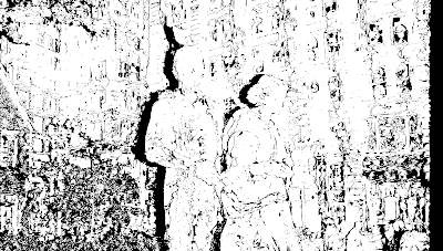
The disparity map is obtained for both the left image and the right image. This provides a way to figure out the occlusions (and pixels where the depth cannot be evaluated accurately) which are shown in the occlusion map.
Let's go over the parameters that control DMAG6's behavior:
- Minimum disparity is the disparity corresponding to the furthest point in the background.
- Maximum disparity is the disparity corresponding to the closest point in the foreground.
I suggest using Disparity Finder 2 (DF2) to get the minimum and maximum disparity. Better yet, you can use Epipolar Rectification 9b (ER9b) to rectify/align the two images (crucial for good quality depth map generation) and get the min and max disparities automatically.
- Alpha is the term that balances the color matching cost and the gradient matching cost. The closer alpha is to 0, the more importance is given to the color. The closer alpha is to 1, the more importance is given to the gradient. In theory, a higher alpha works better when there's quite a bit of texture in the image while a lower alpha works better when the image is relatively flat color wise.
- Truncation value (color) limits the value the color matching cost can take. It reduces the effects of occluded pixels (pixels that appear in only one image).
- Truncation value (gradient) limits the value the gradient matching cost can take. It reduces the effects of occluded pixels (pixels that appear in only one image).
- Truncation value (discontinuity) reduces the penalty when neighboring disparities are different. In the interior of an object, you want the disparities to be pretty much the same assuming the object is in the same depth plane, therefore you want to penalize disparity changes quite a bit. At the boundary of an object where depths can change abruptly, you don't want to penalize the disparity change too much.
I tend to set the truncation value (color) to 20.0 or 30.0, the truncation value (gradient) to 2.0, and the truncation value (discontinuity) to something very large, like 10000.0. Feel free to experiment though!
- Iteration number controls the number of belief propagation iterations at each level.
- Level number controls how many levels the coarse to fine pyramid has. Multi-scale belief propagation means that belief propagation is performed at different levels of the coarse to fine pyramid. The pyramid is built by recursively downsampling the original images.
- Disparity tolerance (occlusion detection). The larger the value, the more mismatch is allowed (between left and right depth maps) before declaring that the disparity computed at a pixel is wrong. Obviously, the larger the value, the less black the occlusion map will look.
- Window radius (occlusion smoothing).
- Sigma space (occlusion smoothing).
- Sigma color (occlusion smoothing).
The parameters that relate to occlusion detection and smoothing should probably be left alone since they only have an effect on the "occluded" pixels, that is, the pixels that show up in black in the occlusion maps.
- Downsampling factor. This parameter enables DMAG6 to run faster by downsampling the images prior to computing the depth maps. If set to 1, the images are used as is and there's no speedup. If set to 2, the images are resized by reducing each dimension by a factor of 2 and DMAG6 should go 4 times faster. The more downsampling is requested, the faster DMAG6 will go, but the more pixelated the depth maps will look upon completion. Downsampling is a quick way to test what parameters do. If downsampling is turned on, the parameters that are spatial, that is, min and max disparity, window radius, window radius (occlusion smoothing), and sigma space (occlusion smoothing) are automatically adjusted to adapt to the level of downsampling that is requested. In other words, you don't have to wonder if you should change those parameters when switching, for example, from downsampling factor = 1 to downsampling factor = 2 as DMAG6 does it automatically for you.
Here's an example:

Left image after rectification.

Right image after rectification.
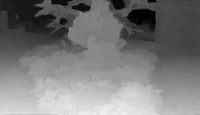
Left depth map obtained with DMAG6 using alpha = 0.9, truncation value (color) = 20., truncation value (gradient) = 10., truncation value (discontinuity) = 10000., iteration number = 5, level number = 5, and lambda = 0.5.
More examples (that compare DMAG6 with DMAG5):
3D Photos - Stevenson tombstone
3D Photos - Civil War reenactors
3D Photos - Looking down at the tombstones
The windows executable (guaranteed to be virus free) is available for free via the 3D Software Page. Please, refer to the 'Help->About' page in the actual program for how to use it.
DMAG6 is similar to Depth Map Automatic Generator 3 (DMAG3). Indeed, DMAG3 is also a "global method" stereo matcher but instead of using belief propagation to minimize the cost function, it uses graph cuts.
The disparity map is obtained for both the left image and the right image. This provides a way to figure out the occlusions (and pixels where the depth cannot be evaluated accurately) which are shown in the occlusion map.
Let's go over the parameters that control DMAG6's behavior:
- Minimum disparity is the disparity corresponding to the furthest point in the background.
- Maximum disparity is the disparity corresponding to the closest point in the foreground.
I suggest using Disparity Finder 2 (DF2) to get the minimum and maximum disparity. Better yet, you can use Epipolar Rectification 9b (ER9b) to rectify/align the two images (crucial for good quality depth map generation) and get the min and max disparities automatically.
- Alpha is the term that balances the color matching cost and the gradient matching cost. The closer alpha is to 0, the more importance is given to the color. The closer alpha is to 1, the more importance is given to the gradient. In theory, a higher alpha works better when there's quite a bit of texture in the image while a lower alpha works better when the image is relatively flat color wise.
- Truncation value (color) limits the value the color matching cost can take. It reduces the effects of occluded pixels (pixels that appear in only one image).
- Truncation value (gradient) limits the value the gradient matching cost can take. It reduces the effects of occluded pixels (pixels that appear in only one image).
- Truncation value (discontinuity) reduces the penalty when neighboring disparities are different. In the interior of an object, you want the disparities to be pretty much the same assuming the object is in the same depth plane, therefore you want to penalize disparity changes quite a bit. At the boundary of an object where depths can change abruptly, you don't want to penalize the disparity change too much.
I tend to set the truncation value (color) to 20.0 or 30.0, the truncation value (gradient) to 2.0, and the truncation value (discontinuity) to something very large, like 10000.0. Feel free to experiment though!
- Iteration number controls the number of belief propagation iterations at each level.
- Level number controls how many levels the coarse to fine pyramid has. Multi-scale belief propagation means that belief propagation is performed at different levels of the coarse to fine pyramid. The pyramid is built by recursively downsampling the original images.
- Disparity tolerance (occlusion detection). The larger the value, the more mismatch is allowed (between left and right depth maps) before declaring that the disparity computed at a pixel is wrong. Obviously, the larger the value, the less black the occlusion map will look.
- Window radius (occlusion smoothing).
- Sigma space (occlusion smoothing).
- Sigma color (occlusion smoothing).
The parameters that relate to occlusion detection and smoothing should probably be left alone since they only have an effect on the "occluded" pixels, that is, the pixels that show up in black in the occlusion maps.
- Downsampling factor. This parameter enables DMAG6 to run faster by downsampling the images prior to computing the depth maps. If set to 1, the images are used as is and there's no speedup. If set to 2, the images are resized by reducing each dimension by a factor of 2 and DMAG6 should go 4 times faster. The more downsampling is requested, the faster DMAG6 will go, but the more pixelated the depth maps will look upon completion. Downsampling is a quick way to test what parameters do. If downsampling is turned on, the parameters that are spatial, that is, min and max disparity, window radius, window radius (occlusion smoothing), and sigma space (occlusion smoothing) are automatically adjusted to adapt to the level of downsampling that is requested. In other words, you don't have to wonder if you should change those parameters when switching, for example, from downsampling factor = 1 to downsampling factor = 2 as DMAG6 does it automatically for you.
Here's an example:

Left image after rectification.

Right image after rectification.

Left depth map obtained with DMAG6 using alpha = 0.9, truncation value (color) = 20., truncation value (gradient) = 10., truncation value (discontinuity) = 10000., iteration number = 5, level number = 5, and lambda = 0.5.
More examples (that compare DMAG6 with DMAG5):
3D Photos - Stevenson tombstone
3D Photos - Civil War reenactors
3D Photos - Looking down at the tombstones
The windows executable (guaranteed to be virus free) is available for free via the 3D Software Page. Please, refer to the 'Help->About' page in the actual program for how to use it.
Sunday, October 12, 2014
Flow-based Delaunay Surface Reconstruction
When you scan a three-dimensional object, you end up with a point cloud (points on the surface of the object). The process of creating a three-dimensional model off that point cloud is called "surface reconstruction". There are many surface reconstruction methods but here, we are gonna focus on methods based on the Delaunay triangulation. Actually, we are even gonna restrict ourselves to methods based on the Delaunay triangulation which carve/sculpt the mesh away. The starting point of such methods is a Delaunay triangulation of the convex hull defined by the point cloud which is then carved away until, hopefully, the mesh accurately represents the scanned object. The pioneering paper on this methodology is: "Surface Reconstruction by Wrapping Finite Sets in Space" by Herbert Edelsbrunner. A more approachable paper is probably: "A geometric convection approach of 3-D reconstruction" by Raphaëlle Chaine. Edelsbruner talks about flow as the driving force of his algorithm. For Chaine, it's convection, but it's basically the same exact thing. So, I think it may be a good idea to refer to this type of approaches as flow-based. Other Delaunay based surface reconstruction approaches include the so-called "crust" algorithms pioneered by Nina Amenta and Marshall Bern but we are not gonna talk about those here.
The process starts with a Delaunay triangulation of the convex hull. In two dimensions, the Delaunay triangulation of a set of points is such that the circumcircle of any element (circle passing through the three vertices of the element) is empty.
Here's an example of the Delaunay triangulation of the convex hull of a point cloud (note that I did this by hand, so I don't actually guarantee it's a Delaunay triangulation but it does look like one):

We basically want to remove elements from the boundary in until we get this (the two-dimensional model in mesh form):

Looking very carefully at the Delaunay triangulation of the convex hull, for a given boundary edge and its unique connected element, the circumcenter (center of the circumcircle) is either on the outside side of the boundary edge or the inside. Any time the circumcenter is on the outside side of the boundary edge, it's an element we probably don't want because it's very likely to be an element that's outside whatever the point cloud is supposed to model. Note that if the vertex opposite the boundary edge is inside the smallest circle passing through the edge's end vertices (we will refer to that circle as the circumcircle of the boundary edge), the circumcenter is on the outside side of the boundary edge and vice versa. This means that we have two ways to tell if an element should be removed. In practice, the latter interpretation of the test is preferred.
The two equivalent ways to tell if an element connected to a boundary edge should be removed:

Here's the pseudo code for the carving or sculpting algorithm that starts from the Delaunay triangulation of the convex hull and ends with the proper (or not so proper) mesh of the two-dimensional model:

Of course, it can't be that easy, all the time. In some cases, the algorithm above may terminate prematurely. Here's an example:

When this happens, the element must be deleted manually or some heuristics based on element size must be used. The algorithm above then continues where it left off. This is clearly the Achille's heal of the method since any decision making based on size can be dicey when sampling is not dense enough.
In three dimensions, things are little bit more complicated but the methodology is exactly the same as in two dimensions. Instead of triangles, the Delaunay triangulation of the convex hull of the point cloud is made up of tetrahedra. The test to see whether an element connected to a boundary face should be removed from the mesh involves either i) computing the circumsphere of the tetrahedron and determining if the circumcenter is on the outside side of the boundary face or ii) computing the circumsphere of the boundary face (the smallest sphere passing through its three bounding vertices) and determining if the vertex opposite the boundary face is inside. Unlike the two dimensional case, there is a bit of a problem when the element connected to a boundary face is bounded by another boundary face. In that case, you can remove the element if both tests (on both boundary faces) tell you that you should remove the element or if just one test (on one of the two boundary faces) tells you that you should remove the element. The former is obviously more aggressive than the later at carving elements away.
Here's the pseudo code for the carving or sculpting algorithm that starts from the Delaunay triangulation of the convex hull and ends with the proper mesh of the three-dimensional model:

In reality, it's a bit more complicated than that since you also have to deal with boundary faces that become disconnected (dangling boundary faces), which may have to be carved away as well (using a methodology similar to the two dimensional case). This may come as no surprise that when all is said and done, you may have to manually delete some elements (or use some potentially dangerous heuristics based on size) and restart in order to get the mesh you really want. The big issue is how much of this manual deleting has to be done. In two dimensions, it may not be too big of a deal but in three dimensions, it may be a problem. Unless there's a "good" automated way to perform those manual deletions, I don't see how a Delaunay based surface reconstruction like this one can be that useful.
What this methodology is lacking is a global view of the problem especially when you have to do manual deletion to "unstuck" the algorithm. It's very hard to tell if an element should be removed (is outside) when all the information at your disposal is very local. This in contrast with another Delaunay-based explicit method called Eigencrust ("Spectral Surface Reconstruction from Noisy Point Clouds" by Ravikrishna Kolluri, Jonathan Richard Shewchuk, and James F. O’Brienwhich) which partitions a graph that connects the elements to find the surface in one global operation (a costly proposition though, clock wise).
Delaunay-based methods like this one are referred to as explicit because there's no surface approximation involved, in other words, the surface passes through points that are actually in the cloud (To be pedantic, the surface is interpolated, not approximated.) This is unlike implicit methods like Poisson or "marching cubes" that approximate the object's surface. Note that those implicit methods need a good normal extrapolation scheme to be effective whereas an explicit method doesn't. If one is able to get decent, consistent with each other normals, a Poisson surface reconstruction ("Poisson Surface Reconstruction" by Michael Kazhdan, Matthew Bolitho and Hugues Hoppe) is extremely hard to beat.
Flow-based Delaunay Surface Reconstruction in Two Dimensions
The process starts with a Delaunay triangulation of the convex hull. In two dimensions, the Delaunay triangulation of a set of points is such that the circumcircle of any element (circle passing through the three vertices of the element) is empty.
Here's an example of the Delaunay triangulation of the convex hull of a point cloud (note that I did this by hand, so I don't actually guarantee it's a Delaunay triangulation but it does look like one):

We basically want to remove elements from the boundary in until we get this (the two-dimensional model in mesh form):

Looking very carefully at the Delaunay triangulation of the convex hull, for a given boundary edge and its unique connected element, the circumcenter (center of the circumcircle) is either on the outside side of the boundary edge or the inside. Any time the circumcenter is on the outside side of the boundary edge, it's an element we probably don't want because it's very likely to be an element that's outside whatever the point cloud is supposed to model. Note that if the vertex opposite the boundary edge is inside the smallest circle passing through the edge's end vertices (we will refer to that circle as the circumcircle of the boundary edge), the circumcenter is on the outside side of the boundary edge and vice versa. This means that we have two ways to tell if an element should be removed. In practice, the latter interpretation of the test is preferred.
The two equivalent ways to tell if an element connected to a boundary edge should be removed:

Here's the pseudo code for the carving or sculpting algorithm that starts from the Delaunay triangulation of the convex hull and ends with the proper (or not so proper) mesh of the two-dimensional model:

Of course, it can't be that easy, all the time. In some cases, the algorithm above may terminate prematurely. Here's an example:

When this happens, the element must be deleted manually or some heuristics based on element size must be used. The algorithm above then continues where it left off. This is clearly the Achille's heal of the method since any decision making based on size can be dicey when sampling is not dense enough.
Flow-based Delaunay Surface Reconstruction in Three Dimensions
In three dimensions, things are little bit more complicated but the methodology is exactly the same as in two dimensions. Instead of triangles, the Delaunay triangulation of the convex hull of the point cloud is made up of tetrahedra. The test to see whether an element connected to a boundary face should be removed from the mesh involves either i) computing the circumsphere of the tetrahedron and determining if the circumcenter is on the outside side of the boundary face or ii) computing the circumsphere of the boundary face (the smallest sphere passing through its three bounding vertices) and determining if the vertex opposite the boundary face is inside. Unlike the two dimensional case, there is a bit of a problem when the element connected to a boundary face is bounded by another boundary face. In that case, you can remove the element if both tests (on both boundary faces) tell you that you should remove the element or if just one test (on one of the two boundary faces) tells you that you should remove the element. The former is obviously more aggressive than the later at carving elements away.
Here's the pseudo code for the carving or sculpting algorithm that starts from the Delaunay triangulation of the convex hull and ends with the proper mesh of the three-dimensional model:

In reality, it's a bit more complicated than that since you also have to deal with boundary faces that become disconnected (dangling boundary faces), which may have to be carved away as well (using a methodology similar to the two dimensional case). This may come as no surprise that when all is said and done, you may have to manually delete some elements (or use some potentially dangerous heuristics based on size) and restart in order to get the mesh you really want. The big issue is how much of this manual deleting has to be done. In two dimensions, it may not be too big of a deal but in three dimensions, it may be a problem. Unless there's a "good" automated way to perform those manual deletions, I don't see how a Delaunay based surface reconstruction like this one can be that useful.
What this methodology is lacking is a global view of the problem especially when you have to do manual deletion to "unstuck" the algorithm. It's very hard to tell if an element should be removed (is outside) when all the information at your disposal is very local. This in contrast with another Delaunay-based explicit method called Eigencrust ("Spectral Surface Reconstruction from Noisy Point Clouds" by Ravikrishna Kolluri, Jonathan Richard Shewchuk, and James F. O’Brienwhich) which partitions a graph that connects the elements to find the surface in one global operation (a costly proposition though, clock wise).
Delaunay-based methods like this one are referred to as explicit because there's no surface approximation involved, in other words, the surface passes through points that are actually in the cloud (To be pedantic, the surface is interpolated, not approximated.) This is unlike implicit methods like Poisson or "marching cubes" that approximate the object's surface. Note that those implicit methods need a good normal extrapolation scheme to be effective whereas an explicit method doesn't. If one is able to get decent, consistent with each other normals, a Poisson surface reconstruction ("Poisson Surface Reconstruction" by Michael Kazhdan, Matthew Bolitho and Hugues Hoppe) is extremely hard to beat.
Saturday, October 11, 2014
View Interpolation (forward and backward mapping/warping)
Given a stereo pair and two depth maps, the problem of getting an intermediate frame is known as view interpolation. The following blurb is very inspired by this academic paper: Fast View Interpolation from Stereo: Simpler can be Better by N. Martin and S. Roy. We are gonna look at two ways to get the interpolated image: forward mapping (warping) and backward mapping (warping). In both cases, an interpolated image using the left image and depth map and an interpolated image using the right image and depth map are built and they are combined to form the final interpolated image. The interpolated image is defined by the parameter alpha (alpha = 0 corresponds to the left image and alpha = 1 corresponds to the right image).
Let's look at how the left and right interpolated images are defined:

Maybe it's easier to grasp if you think about shifting pixels. To get the left interpolated image, you shift the left image's pixels to the left according to the left depth map. To get the right interpolated image, you shift the right image's pixels to the right according to the right depth map. It's as simple as that.
Here's the typical pseudo code to get the left interpolated image using forward mapping:

Clearly, the term xL-alpha*dL(xL) is not an integer in most cases. The easiest way to deal with this problem is to round it to the nearest integer. The hardest way is probably to add color contributions to the 2 nearest pixels on either side of xM'. This is way beyond the scope of this blurb but it is known as "splatting" if you want to delve into it. The resulting interpolated image will have cracks and holes. The cracks come from that nearest integer business (no big deal) and the holes come from scenes in the image that are now revealed.

The right interpolated image can be obtained in a similar fashion. As for the left interpolated image, the right interpolated image will exhibit cracks and holes. When the two are combined, it is hoped that all holes will be filled. In reality, it can be a little bit more complicated than that as, for a a given pixel of the interpolated image, one can decide whether the color information should come from the left image only, the right image only, or both.
As a side note, if you don't have a right depth map and therefore there is no right interpolated image, holes (coming from a left image and a left depth map) are usually filled by getting the first non-empty pixel to the right and using its color to fill the hole, line by line. It's easy to spot as it produces very distinctive streaks. Another option is to propagate its color toward the left but considering the whole image (as opposed to line by line).
The idea behind backward mapping is that, given a pixel xM in the intermediate image, you want to be able to get its color by using linear interpolation on the left (right) image. Because of this, the interpolated image will be guaranteed to have no cracks or holes. It doesn't mean the interpolated image will be perfect. The holes that you would get with a forward mapping won't be there but their filling (inpainting) might not be the best.
Here's some pseudo code to get the left interpolated image using backward mapping (warping):

This above can be done scanline by scanline (Scanline is a fancy way of saying horizontal line.) There might be more than one segment that contains xM. In that case, it's a good idea to consider the segment corresponding to the largest disparity (the most foreground object). Also, the segment search needs only be done within the minimum and maximum disparity (times alpha) that corresponds to the stereo pair.
The right interpolated image can be obtained in a similar fashion. The two interpolated images are then combined to give the final interpolated image.
Let's look at how the left and right interpolated images are defined:

Maybe it's easier to grasp if you think about shifting pixels. To get the left interpolated image, you shift the left image's pixels to the left according to the left depth map. To get the right interpolated image, you shift the right image's pixels to the right according to the right depth map. It's as simple as that.
Forward Mapping (Warping)
Here's the typical pseudo code to get the left interpolated image using forward mapping:

Clearly, the term xL-alpha*dL(xL) is not an integer in most cases. The easiest way to deal with this problem is to round it to the nearest integer. The hardest way is probably to add color contributions to the 2 nearest pixels on either side of xM'. This is way beyond the scope of this blurb but it is known as "splatting" if you want to delve into it. The resulting interpolated image will have cracks and holes. The cracks come from that nearest integer business (no big deal) and the holes come from scenes in the image that are now revealed.

The right interpolated image can be obtained in a similar fashion. As for the left interpolated image, the right interpolated image will exhibit cracks and holes. When the two are combined, it is hoped that all holes will be filled. In reality, it can be a little bit more complicated than that as, for a a given pixel of the interpolated image, one can decide whether the color information should come from the left image only, the right image only, or both.
As a side note, if you don't have a right depth map and therefore there is no right interpolated image, holes (coming from a left image and a left depth map) are usually filled by getting the first non-empty pixel to the right and using its color to fill the hole, line by line. It's easy to spot as it produces very distinctive streaks. Another option is to propagate its color toward the left but considering the whole image (as opposed to line by line).
Backward Mapping (Warping)
The idea behind backward mapping is that, given a pixel xM in the intermediate image, you want to be able to get its color by using linear interpolation on the left (right) image. Because of this, the interpolated image will be guaranteed to have no cracks or holes. It doesn't mean the interpolated image will be perfect. The holes that you would get with a forward mapping won't be there but their filling (inpainting) might not be the best.
Here's some pseudo code to get the left interpolated image using backward mapping (warping):

This above can be done scanline by scanline (Scanline is a fancy way of saying horizontal line.) There might be more than one segment that contains xM. In that case, it's a good idea to consider the segment corresponding to the largest disparity (the most foreground object). Also, the segment search needs only be done within the minimum and maximum disparity (times alpha) that corresponds to the stereo pair.
The right interpolated image can be obtained in a similar fashion. The two interpolated images are then combined to give the final interpolated image.
Saturday, October 4, 2014
3D Photos - Montreal subway station
Here, I am gonna demonstrate what effects alpha and the truncation value have on the depth map when using Depth Map Automatic Generator 5 (DMAG5). The closer alpha is to 0, the more the dissimilarity between potential matching pixels comes from the color of the pixels. The closer alpha is to 1, the more the dissimilarity between potential matching pixels comes from the color gradient. The color gradient is usually preferred due to difference in illumination between the left and right images. The truncation is there to reduce the effects of occlusions. Maybe have a look at Fast Cost Volume Filtering for Stereo if you need more explanations about those parameters.

Left image.

Right image.
The minimum disparity is set at -28 and the maximum disparity at 0. Unless indicated otherwise in the following captions, the radius is 12, alpha is 0.9, the truncation value for the color is 7, the truncation value for the gradient is 2, the value for epsilon is 4, and the number of smoothing iterations is 1.

Depth map.

Depth map with alpha = 0.5.

Depth map with alpha = 0.1.
Let's go back to alpha = 0.9.

Depth map with truncation (gradient) = 4.

Depth map with truncation (gradient) = 8.
3D Photos - Boston statue with pigeon
Here, I am gonna demonstrate what effect the window radius has on the depth map when using Depth Map Automatic Generator 5 (DMAG5).

Left image.

Right image.
This statue in Downtown Boston is actually part of the Boston Irish Famine Memorial.
The width of the images in the above stereo pair is 1200. They were resized and aligned in StereoPhotoMaker (The alignment part is quite important.) The minimum and maximum disparities were obtained with Disparity Finder 2 (DF2). For the record, the minimum disparity is -32 and the maximum disparity is 0. I did four runs with DMAG5 using the default settings changing only the window radius (3, 6, 12, 24, 36, and 48). The great thing about DMAG5 is that the cpu time spent is not a function of the window radius, which was not the case for Depth Map Automatic Generator 2 (DMAG2) which gives depth maps that are similar to DMAG5.

Depth map with window radius = 3 (0.25% of the width).

Occlusion map with window radius = 3.

Depth map with window radius = 6 (0.5% of the width).
Occlusion map with window radius = 6.

Depth map with window radius = 12 (1% of the width).

Occlusion map with window radius = 12.

Depth map with window radius = 24 (2% of the width).

Occlusion map with window radius = 24.

Depth map with window radius = 36 (3% of the width).

Occlusion map with window radius = 36.

Depth map with window radius = 48 (4% of the width).

Occlusion map with window radius = 48.

Left image.

Right image.
This statue in Downtown Boston is actually part of the Boston Irish Famine Memorial.
The width of the images in the above stereo pair is 1200. They were resized and aligned in StereoPhotoMaker (The alignment part is quite important.) The minimum and maximum disparities were obtained with Disparity Finder 2 (DF2). For the record, the minimum disparity is -32 and the maximum disparity is 0. I did four runs with DMAG5 using the default settings changing only the window radius (3, 6, 12, 24, 36, and 48). The great thing about DMAG5 is that the cpu time spent is not a function of the window radius, which was not the case for Depth Map Automatic Generator 2 (DMAG2) which gives depth maps that are similar to DMAG5.

Depth map with window radius = 3 (0.25% of the width).

Occlusion map with window radius = 3.

Depth map with window radius = 6 (0.5% of the width).

Occlusion map with window radius = 6.

Depth map with window radius = 12 (1% of the width).

Occlusion map with window radius = 12.

Depth map with window radius = 24 (2% of the width).

Occlusion map with window radius = 24.

Depth map with window radius = 36 (3% of the width).

Occlusion map with window radius = 36.

Depth map with window radius = 48 (4% of the width).

Occlusion map with window radius = 48.
Subscribe to:
Posts (Atom)