We are gonna interlace 6 images or frames with Superflip. All frames are the same size: 3512x2422 pixels. At a resolution of 600 ppi, the physical size of the frames is thus 5.853x4.037 inches. The physical size is thus close to 6x4 inches but not quite (to keep things interesting).
If frame0 corresponds to the left image (of a stereo pair) and frame5 corresponds to the right image, you want frame5 to be at the top and frame0 at the bottom. This is because, in the back of a lenticular lens, you want the left frames to be on the right and the right frames to be on the left (mirror effect).
Let's click "Process" and see what we get:
I keep "Preserve Aspect Ratio" checked so that if I change the width of the output image, the height is automatically modified. Here, I do not "Calculate Output Size from Input Size" but simply set the width I want in "Width (inches)". I have also set the Line Screen (LPI) to 60.12 because that's my visual pitch. The "Alignment Marks" is checked and, in the Alignment Mark Options, I have chosen to have alignment marks only at the top and bottom.
At this point, I have not checked "Resample Output with banding eliminator".
If you were to hit "Process" and save the interlaced file, you will find that the interlaced file is 2160x1673 pixels with a resolution of 360.720 (physical size is thus 5.988x4.638 inches).
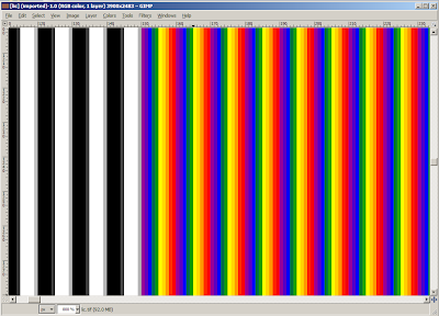
That's a closeup of the interlaced file. So, yeah, frame0 is red, frame1 is orange, frame2 is yellow, frame3 is green, frame4 is blue, and frame5 is purple. The black and white stripes on top are the alignment marks. You can clearly see that there are 6 pixels for each lens, each pixel coming from one frame, with zero interpolation. With a lpi of 60.12, this gives us a resolution of 6x60.12=360.72 pixels per inch (ppi) for the interlaced image. That's good but my printer has a resolution of 600 dpi, so we're gonna need to resample at some point. We either let the printer driver do its own resampling or we do it in Superflip. Let's do it within Superflip!
Side note: I would have expected one sequence of purple/blue/green/yellow/orange/red strips to fall exactly under one sequence of black/white strips, but it does not. It's the blue/green/yellow/orange/red/purple sequence that falls under the black/white sequence. Weird! That would have been a little helpful in centering the printed interlaced image under the lens.
I have now checked "Resample Output with banding eliminator" with a resolution (resample ppi) of 600. Of course, the width and height in inches of the output file have changed to reflect that. If you were to hit "Process" and save the interlaced file, you will find that the interlaced file is 3593x2783 pixels with a resolution of 600 (physical size is thus 5.988x4.638 inches).
So, we now have the interlaced image at the right physical size (6 inches wide or very close to it) and the right resolution for our printer (600 dpi) but, obviously, there has been some interpolation going on between neighboring frames (Compare with the non-interpolated image!) The interpolation is best seen in the alignment marks at the top.
Basically, Superflip uses a pretty simple algorithm to interlace. If you have 6 frames, it's gonna pick a column of pixels from each frame like so:
- Take column 1 from frame5,
- take column 2 from frame4,
- take column 3 from frame3,
- take column 4 from frame2,
- take column 5 from frame1,
- take column 6 from frame0,
- take column 7 from frame5,
- take column 8 from frame4, etc.
The end result is a file that has the same size (pixel wise) as the frames. When you specify a physical size (in inches) for the output file, Superflip is gonna change the resolution (the ppi) so that physical size in inches x resolution = size in pixels. Now, when you change the resolution by checking the "Resample"check box, Superflip resamples the output file. The end result is a file that looks a bit blurred (due to the interpolation) but at the correct resolution and physical size (in inches). I am hoping the interpolation algorithm never blurs stripes from frame5 and frame0 (the two extreme frames) which are next to each other in the non-interpolated interlaced file. I mean it's ok to blur adjacent stripes from frames that are under the same lens but I don't think it's a good idea to blur stripes from frames that are adjacent but are not under the same lens. By looking at the RGB values of the reddish stripes, you can see that they get some blue, which means that the purple (frame5) and red (frame0) are being blurred. This unfortunately means that the interpolation algorithm used in Superflip goes across adjacent lenses.
I am not completely sure whether it's best to:
1) not resample in Superflip and let the printer driver do the interpolation (or do the interpolation somewhere else like Photoshop or Gimp), or
2) resample in Superflip hoping the printer driver will not interpolate anything.
My guess would be that it's better to resample in Superflip, although it might be better to not resample in Superflip and let Photoshop and Gimp handle the resampling with an appropriate interpolation algorithm.
Even though this post is about Superflip, it is interesting to see what LIC does with the same input.
That's basically what LIC looks like. All I did was give the lpi, the resolution, and the width of the image I want (6 inches). I also asked for registration marks on both sides, which adds 0.25 inch on each side (the width of the final image will actually be 6.5 inches, not 6 inches). LIC is much easier to use than Superflip, obviously. But is it as good?
This is the interlaced file showing the registration marks on the left. There's definitely some interpolation going on but it is not as severe as with Superflip. Which interpolation is better (between Superflip and LIC)? I would tend to think that LIC has a better interpolation scheme, but deep inside, I don't really know (Your thoughts are welcome.) If we look a bit deeper and focus on the purple tinged strip between the red strip (rgb=255,0,0 aka frame0) and the purple strip (rgb=152,0,152 aka frame5), we can see that it has taken color from both its neighbors, meaning the interpolation is crossing over the lenticules. But, unlike Superflip, the two strips on either side (the red and purple strips) have not been interpolated at all. This, I believe, is a good thing.
I have used both Superflip and LIC, and there's not that much difference in the end product. Note that I only do small lenticulars (6x4 inches) and I am not a professional.


