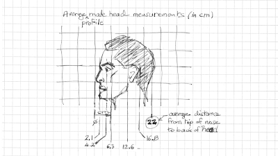
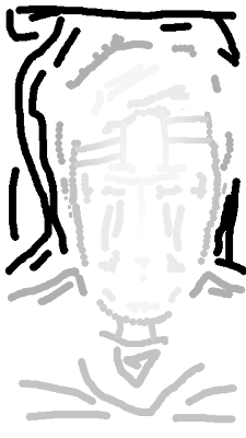
To generate the sparse depth map needed by DMAG4 (made up of "clumsy" brush strokes), I made use of key measurements of the human head when viewed in profile:

Key dimensions of the average human male head in profile. The drawing, grid included, is a copy of a drawing in "Drawing the Head and Hands" by Andrew Loomis.
Then I set up a correspondence between gray levels (recall that 255 is white and 0 is black) and distances (in cm):
255 -> 0 cm
245 -> 2.1 cm
235 -> 4.2 cm
225 -> 6.3 cm
...
Then I went to work in Gimp using the pencil tool on a transparent layer:

This is the sparse depth map ready to be fed into DMAG4. Note that the white areas are really transparent. In gimp, those areas show up with a checkerboard pattern but here, on blogger, they show up as white (red in DMAG4).
In Gimp, there are a few things you kinda need to know in order to make your life just a bit easier when working on a sparse depth map:
1) How to create a gradient driven brush stroke between two already colored areas? Click on "Dynamics"->"Color from Gradient" in the pencil tool options, use the eye dropper tool so that the foreground color corresponds to your start point, use the eye dropper tool to make the background color your end point, and draw with the pencil from the start point to the end point. The brush stroke will have a gradient that goes from the foreground color to the background color. You can control the fade from foreground color to background color with the "Fade length" slider under "Dynamics Options" in the pencil toolbox.
1b) How to fill a selected area with a color gradient? I think this is a much better way to do gradient stuff than what's described in 1). What you do is make a polygonal selection with the "Free Select Tool", choose a foreground and background color, and then use the "Blend Tool" to create a gradient fill between a foreground color and the background color within your selected area. Note that the gradient fill is gonna be anti-aliased so you will want to do 3) at some point.
2) How to use the eraser? That's easy enough, just pick up the eraser tool but make sure you check the "Hard edge" box in the eraser tool options.
3) How to make all the pixels in a layer either fully transparent or fully opaque? If, for whatever reason, some pixels in the layer are not semi-transparent due to anti-aliasing shenanigans, you need to make those semi-transparent pixels either fully transparent or fully opaque. That's easy enough if you click on "Layer"->"Transparency"->"Threshold Alpha ...", and click OK. Now, all your pixels in the layer are either transparent or opaque. DMAG4 checks for the presence of semi-transparent pixels in the sparse depth map and complains vividly if there are some.
It took me a couple of iterations of going into Gimp and running DMAG4 to get this dense depth map. Between Gimp and DMAG4, I also use Gimpel3D to "visualize" the depth map in 3d and make corrections to the sparse depth map which I then re-feed into DMAG4 (I use Gimpel3d just for visualization purposes although it could be used for much more).
In Gimpel3d, use the "Single Frame" tab to load the reference image ("Load Fresh Frame") and the depth map ("Import Depth Mask"). Note that you may have to flip the image and the depth map vertically in the "Image Settings" tab if they are upside down (you either do nothing or you flip them both). To view the scene in 3Dd click on the "3D" button. Use the combo "Alt"+"left mouse button" to rotate and "Alt"+"right mouse button" to zoom in or out. To control the depth, first click on "Default Layer" (the scene will get a red border) in the lower right menu and then click on "Depth" in the upper right menu. Moving the slider will change the depth of the scene.
Gimpel3d can be used to get the left and right images, assuming the reference image is the center image. Before doing that, you may want to change the location of the viewing plane (defines the stereo window) and/or the eye separation (determines the severity of the stereo effect). Click on "Views"->"Show Camera" to see where the camera and the viewing plane are. To change the location of the viewing plane, click on "Stereo Settings" in the upper right menu and move the slider for the "Focal Length". To change the eye separation, move the slider for "Eye Separation". The "Linear Scale" slider maintains the ratio between the focal length and the eye separation. Click on "File"->"Export Files" to get to the export options screen and click on "Save Left" to save the left image and "Save Right" (bottom row of buttons below "Export Current Frame Only") to save the right image. You can also save the anaglyph with "Save Anaglyph". I do have however the impression that what Gimpel3d calls the left image is actually the right image and vice versa. Indeed, the right image should have a gap fill on the right side and the left image should have the gap fill on the left. Here, I am getting the opposite effect and that's quite odd. In any case, this is to be verified. For this particular case, not that the reference image and depth map had to be flipped vertically, maybe that's got something to do with it.

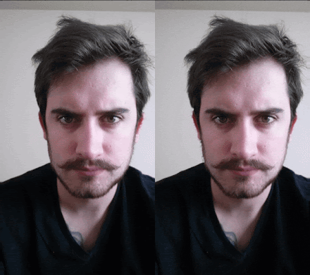
Animated GIF created in StereoPhoto Maker (as is, without changing the location of the viewing plane) switching between the left and right images.
If you want to generate more frames for a smoother animated GIF or a lenticular, the easiest way is probably to keep reducing the eye separation in Gimpel3d and save the left and right images.


No comments:
Post a Comment